Shape Library
Choose the shape that most closely matches your gasket. The drawing, dimensions, and tips below will update to match your selection.
The most common gasket form. A flat annular ring that sits between two flanges inside the bolt circle.
A ring face gasket with bolt holes is called a full face gasket.
A blind gasket has no centre bore. When combined with bolt holes, it becomes a full face blind (cap) gasket.
A solid disc with bolt holes -- used to cap off unused flanges or blank pipe ends.
Ring Face Gasket
Also known as: IBC / RF / Raised Face / Washer
Standard ring that sits inside the bolt circle. The most common gasket geometry for pipe flanges, valves, and pumps.
Full Face Gasket
Also known as: FF / Full Faced
Spans the full flange face including bolt holes for alignment. Used on flat face flanges and large-diameter applications where precise location is important.
Full Face Blind Gasket
Also known as: Blank / Cap Gasket
A solid disc with bolt holes and no centre bore. Used to cap off unused flanges, dead-end pipe runs, or blank test points.
Circle
A circle. Need a description? It's circular. Has a diameter. Or a radius, if you want to be fancy.
There are two common ways to specify bolt hole positions on rectangular gaskets. Either method works -- we are not picky.
Pitch method: Specify the centre-to-centre distance between adjacent holes (the "pitch"), plus the offset of the first hole from the gasket edge (the "starting point"). Horizontal and vertical pitch may differ.
Span method: Specify the total distance from the first hole centre to the last hole centre along each edge, plus the number of holes. The pitch is then calculated from the span.
Also known as: Picture Frame / Frame Gasket / Square
A rectangular frame with a rectangular opening. Used for non-circular joints like heat exchangers, access covers, and inspection hatches.
Oval Gasket
Also known as: Elliptical / Manway / Egg Shape
An elliptical ring gasket. Common for manway openings, boiler handways, and non-standard oval flanges. Defined by long axis, short axis, and cross section width.
Obround Gasket
Also known as: Racetrack / Stadium / Discorectangle
Two parallel straight sides joined by semicircular ends. Common in boiler handway openings, elongated ports, and stadium-shaped flanges.
2-Bolt Flange Gasket
Dog-bone (or dumbbell) profile — two circular ears at each bolt position connected by tangent body arcs around a central bore. Common in SAE hydraulic connections and small-bore exhaust systems.
3-Bolt Flange Gasket
Triangular body with large radiused corners and straight sides. The standard form for high-performance exhaust and turbocharger flanges.
4-Bolt Flange Gasket
Square or rectangular body with large radiused corners. Commonly seen in automotive intake and water pump applications.
Strip Gasket
Also known as: Tape / Flat Strip / Packing Strip
A simple flat strip or tape. The most basic gasket form -- just material cut to length and width. Common for door seals, duct joints, and any application where a straight run of material is needed.
Dimension Reference
These are the dimensions relevant to your selected shape. Each abbreviation corresponds to a callout on the drawing above.
The full outer diameter of a circular gasket, measured edge to edge through the centre.
The diameter of the central bore opening, measured edge to edge through the centre.
The diameter of the imaginary circle passing through the centres of all bolt holes.
Total count of bolt holes. Assumed equally spaced unless otherwise noted.
Diameter of each bolt hole. Typically 2–3 mm larger than the bolt shank.
The full external length of a rectangular gasket.
The full external width of a rectangular gasket.
The length of the internal rectangular opening.
The width of the internal rectangular opening.
The radius of rounded corners. Always specify both inner and outer radii if they differ.
The longest overall diameter of an oval shape, measured end to end through the centre. This is the outside dimension. If you know the inside opening instead, provide that along with the cross section width.
The shortest overall diameter of an oval shape, measured side to side through the centre. This is the outside dimension. If you know the inside opening instead, provide that along with the cross section width.
The face width of the sealing surface -- the distance from the outer edge to the inner edge of the gasket ring. Also called flange width.
The overall outside length of the gasket, measured end to end. For obround gaskets, if you know the inside opening length, provide that along with the cross section width instead.
The overall outside width of the gasket. For obround gaskets, if you know the inside opening width, provide that along with the cross section width instead.
The centre-to-centre distance between the two bolt holes on a 2-bolt flange.
Material thickness. Measure with calipers at multiple points -- gaskets compress unevenly with age.
How to Measure
No drawing? Worn gasket? Measuring off the flange? All three starting points work — use whichever fits what you have in front of you.
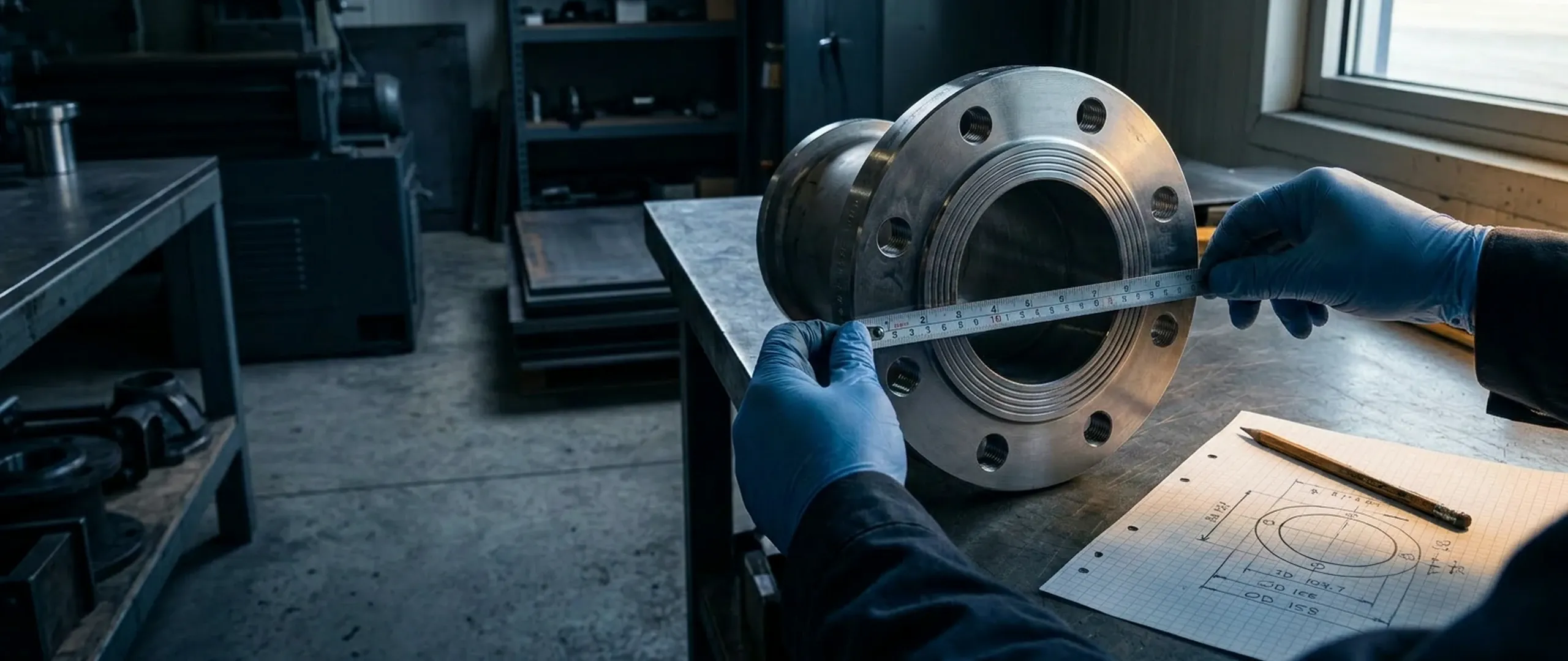
From an Existing Gasket
- -- Lay the gasket flat on a clean, level surface
- -- Measure all key dimensions (see drawing above)
- -- Take perpendicular readings to check for ovality or distortion
- -- Measure thickness at 3+ points with calipers
- -- Photograph with a ruler for scale
From the Flange
- -- Measure the sealing face dimensions (these become the gasket outer dimensions)
- -- Measure the bore or port opening (this becomes the gasket inner dimension)
- -- Count bolt holes, measure hole diameter and positions
- -- Note the flange standard if known (AS 2129, ANSI, BS, PN, JIS)
- -- Check for gasket grooves, raised faces, or locating features
From a Drawing
- -- Send us a DXF, DWG, PDF, STEP, or dimensioned sketch
- -- DXF and DWG files go straight to CNC -- zero re-drawing needed
- -- Ensure all critical dimensions are clearly called out
- -- Specify material type, thickness, and any tolerances
- -- Include corner radii, hole sizes, and any special features
What We Need From You
No matter how you provide information, here is what we need to manufacture your gasket:
Shape + Dimensions
All the critical measurements shown in the drawing above for your selected shape.
Material
The gasket material type, or the application so we can recommend one.
Thickness
Material thickness in millimetres. If unsure, tell us the application and we will advise.
Quantity
How many you need. We manufacture from 1 piece upward with no minimum order.
Measurement Tips
These tips are filtered to your selected shape. Follow them for the most accurate results.
Lay It Flat
Always measure gaskets on a clean, flat surface. A gasket measured while held in the air or draped over an edge will give distorted readings, especially for thin or flexible materials.
Use the Right Tool
Use digital calipers or a steel rule for anything under 300 mm. Fabric tapes stretch. Wooden rules warp. For larger gaskets, a steel tape measure works, but always double-check critical dimensions.
Take Multiple Readings
Measure each critical dimension more than once. Averaging multiple readings reduces error and highlights variations -- if readings differ significantly, note the range so we can account for wear or distortion.
Cross-Check for Ovality
Take diameter readings at two perpendicular positions (9-to-3, then 12-to-6). Old flanges warp, bolts pull unevenly, and gaskets compress over time. If the two readings differ, the joint is out of round -- note both values so we can compensate.
Measuring PCD Correctly
PCD is centre-to-centre of bolt holes, not edge-to-edge. For gaskets with an even number of holes: measure from the inside edge of one hole to the outside edge of the diametrically opposite hole. This equals the PCD.
Check for Squareness
Measure both diagonals of a rectangular gasket. If they differ significantly, the gasket or flange has gone out of square. Note both diagonal measurements so we can compensate.
Don't Overthink It -- We're Here to Help
Everything on this page is here to help you get the best result, but at the end of the day, our experienced drafting team has seen it all. We routinely turn rough sketches, phone descriptions, and even photos of napkin drawings into precision-cut gaskets.
What works for us
- -- A quick phone call -- our team can walk you through the measurements in minutes
- -- A sketch on paper (or a napkin) with key dimensions noted
- -- A photograph of the old gasket or flange with a ruler for scale
- -- A digital file (DXF, DWG, PDF, STEP) -- goes straight to CNC, zero re-drawing
- -- The physical part posted to us -- we will reverse-engineer it
Useful tools
- Manufacturing Tolerances -- check our standard tolerances, or specify tighter ones if needed
- Standard Dimensions -- if your gasket matches a standard flange, just tell us the standard and size
- Contact Us -- call, email, or use the form -- we respond fast
Reverse Engineering & Digital Metrology
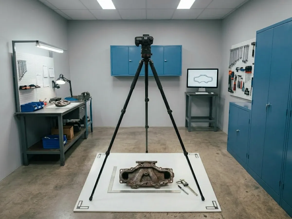
When drawings are unavailable or dimensions are difficult to capture, send us the physical part. Our workshop is equipped for reverse engineering -- we will measure, digitise, and produce a manufacturing file from your sample.
We use digital calipers, optical comparators, and coordinate measuring tools to capture complex profiles accurately. The resulting drawing becomes your permanent reference for reorders.
Send the physical part when the original documentation is gone or the gasket is too worn to measure accurately — we measure the flange directly and produce a manufacturing file from scratch.
Standard Sizes
If your gasket matches a recognised flange standard, you may not need to measure at all. Just tell us the standard, table, size, and material.
Standard Dimensions Table
Browse our searchable database of gasket dimensions for AS 2129, AS 4087, ANSI/ASME B16.21, BS 3381, BS 10, PN/EN 1514, and JIS standards.
Browse standard dimensionsGasket Profile Generator
Build a gasket specification interactively by selecting your standard, size, material, and options. Generates a complete quote-ready specification.
Launch the generatorExplore Further
Disclaimer
This guide is provided for general engineering reference only and does not constitute professional advice, specification, or guarantee of performance. Actual results depend on specific application conditions. Universal Gaskets Pty Ltd accepts no responsibility or liability for decisions made based on this information. For full terms, see our Terms & Conditions.
Dimensions and measurement techniques may vary with your specific application, equipment condition, and operating environment. When in doubt, contact our team for assistance — we are happy to verify dimensions and recommend the best approach for your application.