
Manufacturing Tolerances
DIN 7715-5, ISO 3302-1, and ISO 2768-1 general tolerances for gasket manufacturing. Interactive tolerance checker, reference tables, and practical guidance across cut, extruded, and rigid materials.
Choosing the Right Standard
This page covers the four tolerance standards that apply to gasket manufacturing, with reference tables and an interactive checker to confirm the right choice for your application.
Why it matters: when a drawing specifies the wrong standard, or an unnecessarily tight precision class, you get rejection disputes, rework, and higher costs for no improvement in seal performance. The correct standard depends on the material being manufactured.
Three standards cover most of what we manufacture: DIN 7715-5 for cut rubber and soft sheet, ISO 3302-1 for extruded rubber profiles, and ISO 2768-1 for rigid materials. A fourth standard — ARPM (Association for Rubber Products Manufacturers, formerly RMA) — applies specifically to die-cut rubber parts and is common on US-origin drawings.
P2
Cut Soft & Elastic
DIN 7715-5 P2 — our default unless your drawing specifies otherwise.
E2
Extruded Rubber
ISO 3302-1 E2 — our default unless your drawing specifies otherwise.
m
Rigid & Semi-Rigid
ISO 2768-1 Class m — our default unless your drawing specifies otherwise.
DIN 7715-5
Cut parts — soft & elastic
For parts cut or punched from rubber and soft sheet materials. Defines tolerance classes P1, P2, P3 that account for flexibility and compressibility during cutting and measurement.
ISO 2768-1
Rigid & semi-rigid materials
General tolerances for linear and angular dimensions. Defines Fine, Medium, Coarse, and Very Coarse classes for dimensionally stable materials: metals, PTFE, and engineering plastics.
ISO 3302-1
Extruded rubber profiles
Dimensional tolerances for extruded rubber profiles (E classes for cross-section, L classes for cut length). Applicable to EPDM seals, silicone strips, and custom-profile extrusions.
ARPM / RMA
Die-cut rubber (US system)
The American system for die-cut rubber tolerances, graded by precision from Class 1 (High Precision) to Class 3 (Commercial). Common on US-origin drawings and broadly comparable to DIN 7715-5 for solid rubber, though there is no exact one-to-one mapping.
Standard Selection by Material
DIN 7715-5 · Cut Soft Parts
Natural rubber (NR), Nitrile (NBR)
EPDM, Neoprene (CR), Viton (FKM)
Silicone (VMQ), Butyl (IIR)
Foam & sponge rubber, cork rubber
ISO 2768-1 · Rigid Materials
Metals & alloys (316SS, aluminium)
PTFE, POM (Delrin), nylon
Phenolic, polycarbonate, rigid PVC
UHMWPE, glass-filled composites
ISO 3302-1 · Extruded Profiles
EPDM profiles & seals
Silicone strips & tubing
Neoprene extrusions
Custom-profile rubber sections
Extrusion tolerances are determined by the manufacturing process (die swell, vulcanisation shrinkage), not by material hardness. The same rubber compound will have different tolerances when cut from sheet versus extruded as a profile.
Why Material Matters
Soft and elastic materials deform under measurement pressure. Calipers can unintentionally compress a rubber gasket, making tighter tolerances difficult to verify reliably. DIN 7715-5 accounts for this by defining tolerances that we can reliably achieve in cutting and confidently verify during inspection.
Extruded rubber profiles have their own dimensional challenges: die swell, shrinkage during vulcanisation, and cross-sectional variation along the length. ISO 3302-1 E classes address these specific process characteristics separately from the material-hardness continuum.
For rigid materials (metals, PTFE, and engineering plastics), ISO 2768-1 is appropriate because they are dimensionally stable and we can measure them accurately with standard instruments.
Reference Tables
Full tolerance tables for all three standards. Selecting a material type in the Tolerance Checker below switches the active tab here.
DIN 7715-5 — Cut Part Tolerances
Permissible deviations for parts cut, punched, or punch-cut from rubber and soft sheet materials. All values in mm unless noted.
Click a class card to highlight its column. Click again to deselect.
Source: DIN 7715 Part 5: Tolerances for cut, punched, and punch-cut rubber parts from sheets/plates. First published in the 1970s, DIN 7715-5 is a long-standing standard whose P-classes remain the de-facto industry reference for cut rubber parts.
ISO 3302-1 — Rubber Dimensional Tolerances
The international standard for dimensional tolerances on moulded, extruded, and calendered rubber products. The tables below cover E classes (extruded cross-sections) and L classes (cut lengths), the two most relevant to gasket and seal profiles we manufacture. All values in mm unless noted.
Click a class card to highlight its column. Click again to deselect.
Source: ISO 3302-1, Rubber tolerances for products, Part 1: Dimensional tolerances (E classes for extruded profiles).
Extrusion Cut-Length Tolerances (L Classes)
If you are specifying the cut length of an extruded profile, these tolerances apply separately from the cross-sectional tolerances above. All values in mm unless noted.
Source: ISO 3302-1, Rubber tolerances for products, Part 1: Dimensional tolerances (L classes for cut lengths of extruded profiles).
What Else ISO 3302-1 Covers
ISO 3302-1 also defines tolerance classes for moulded rubber, mould flash and finish, calendered sheet thickness, and die-cut parts that we have not reproduced on this page:
- M classes (M1–M4) — moulded rubber dimensions, with separate values for Fixed (F) and Closure (C) dimensions.
- X classes (X0–X5) — flash height and extension on moulded parts, from precision (X1, ≤0.10 mm) to non-critical (X5, no limit).
- F classes (F1–F4) — ARPM mould-surface finish grades, from polished (F1, Ra ≈0.4 µm) to dull blasted (F4).
- ST classes (ST1–ST3) — calendered sheet thickness tolerances. Sheet supplier sets the grade for stock material.
- Die-cut & waterjet-cut classes — length and width tolerances for punched parts, graded by precision. US-origin drawings often call these up as RMA / ARPM classes (see below).
- ISO 3601-1 / ISO 3601-3 — O-ring dimensional tolerances and quality acceptance criteria (Class A/B, Grade N/S/CS).
We can manufacture and inspect to any of these classes on request — the tables on this page show the most commonly referenced grades for the work we do day to day. If your drawing calls out a class we have not tabulated here, include it in your enquiry and we will quote against it directly.
ISO 2768-1 — General Tolerances
The international standard for general tolerances on linear and angular dimensions without individual tolerance indications. Australian engineering drawings widely reference ISO 2768-1 as the general tolerance standard for rigid materials; AS 1100 governs drawing practice but publishes no competing general-tolerance table. These tolerances apply to dimensions that do not carry an individual tolerance callout on a drawing, and are appropriate for rigid, dimensionally stable materials.
Click a class card to highlight its column. Click again to deselect.
Linear Dimensions
External Radii & Chamfer Heights
Angular Dimensions
1° = 60 minutes of arc (60')
Tolerance Checker
Enter your material type, tolerance class, and nominal dimension to instantly look up the applicable tolerance. Results reference the full tables above.
Step 1 — Material Type
Step 2 — Tolerance Class
Step 3 — Nominal Dimension
Result
Tolerance
Minimum
Maximum
Matched range: (percentage-based for this range)
Quote to this tolerance →No tolerance data available for this dimension and class combination. Check the reference tables above or contact our team for guidance.
Cost vs Precision
Tighter tolerances increase cost through slower cutting speeds, additional quality checks, and higher reject rates. P2 / E2 / Medium is appropriate for the vast majority of gasket applications. Reserve finer classes for critical seal interfaces where dimensional accuracy genuinely affects performance.
Standard Comparator
Drawings frequently call out ISO 2768-1 (the general machining standard) for soft rubber gaskets, specifying a tolerance band that's difficult to verify reliably on compressible materials. This table compares ISO 2768-1 Class m and DIN 7715-5 P2 across common gasket dimension ranges to show how much the two standards differ. The DIN column shows the span of P2 bands that fall within each ISO range. ISO 3302-1 E2 (extruded rubber) tolerances generally fall between these two, closer to the DIN values.
What This Means
DIN 7715-5 P2 allows 2–5× wider tolerances than ISO 2768-1 Class m for the same dimension range. This isn't a sign of poor quality; it reflects the physical reality of cutting and measuring soft, compressible materials.
If your drawing specifies ISO 2768-1 Class m for a soft rubber gasket: The gasket will still seal perfectly within DIN 7715-5 P2 tolerances. Applying ISO 2768-1 Class m to soft materials creates unnecessary rejection risk and higher costs — with no improvement in seal performance. The material simply cannot be measured to that level of confidence. We recommend discussing tolerance requirements with our team.
There is a second reason the wider band is rarely a problem in a bolted joint. Gasket bolt holes are clearance holes, and the flange's own position tolerance already allows more movement than a P2 profile band. ASME B16.5 permits ± 1.5 mm on the bolt-circle diameter and ± 0.8 mm between adjacent holes — both wider than the P2 tolerance on a comparable gasket dimension. Tightening the gasket band does not tighten the assembly; the flange geometry governs the fit.
RMA / ARPM Die-Cut Standards
The ARPM (formerly RMA) die-cut tolerance standard is also graded by precision, though it uses its own class system and its own tolerance tables. US-origin drawings typically call up RMA / ARPM Class 1 (High Precision), Class 2 (Precision), or Class 3 (Commercial), with separate tables for each product form (solid, sponge, and closed-cell rubber).
Class 1 — High Precision
The tightest ARPM die-cut grade. Specified where dimensional control on the cut profile is critical.
Class 2 — Precision
The commercial grade most often called up for die-cut gasket work, and the closest fit to how we cut day to day.
Class 3 — Commercial
The most open grade, for high-volume die-cut parts where cost is the primary driver.
How Do ARPM and DIN Compare?
For solid rubber, ARPM tolerances are broadly comparable to DIN 7715-5 P2/P3 across common dimension ranges. Both standards grade by precision, but the two systems use different naming and different underlying tables, so a direct 1:1 mapping is not technically exact.
If your drawings reference ARPM or RMA classes, include the full class callout in your enquiry. We manufacture to DIN 7715-5 and can confirm the practical equivalence for your specific application.
Working From a US Drawing?
Send us the exact ARPM / RMA class and product form as written on the drawing. We cut to DIN 7715-5 and can confirm the closest workable equivalent for your part, rather than guessing at a conversion.
Practical Guide
Specifying the right tolerance class isn't just about reading a table. It depends on what the material does under the cutter and under the caliper. Here's what you need to know about the factors that determine which class is realistic for your parts.
Material Considerations
Rigid Materials
Metals, engineering plastics (e.g. nylon, polycarbonate, PTFE), rigid composites
Dimensionally stable and repeatable under measurement. We apply ISO 2768-1 classes directly to these materials, and our CNC cutting reliably achieves Fine or Medium class.
Soft & Elastic Materials
Rubber, silicone, foam, soft polyurethane, cork rubber composites
Shore hardness directly affects what we can reliably achieve, which is why we apply DIN 7715-5, not ISO 2768-1, to these parts.
Thermal Expansion
All materials, especially polymers
Polymers expand significantly more than metals when heated, typically 5–15 times more. Parts we manufacture within tolerance at ambient temperature may measure at different dimensions after transport, storage, or in service.
Moisture Absorption
Paper-based gaskets, cork composites, compressed fibre materials
Hygroscopic materials absorb moisture from the environment, causing dimensional swelling of up to 3% (grade-dependent). Parts may measure within tolerance when we dispatch them, but can drift as they equilibrate to ambient conditions at your site. This is typically the larger environmental effect.
What the Cutting Process Can Hold
Different cutting methods hold different tolerances. The figures below are typical published industry capability, shown for orientation only — the tolerance that applies to your part is set by the tolerance class on your drawing and confirmed at quotation, not by the cutting method alone.
Typical published industry capability, for orientation only — not a quoted specification. Your part's tolerance is set by its drawing class and confirmed at quotation.
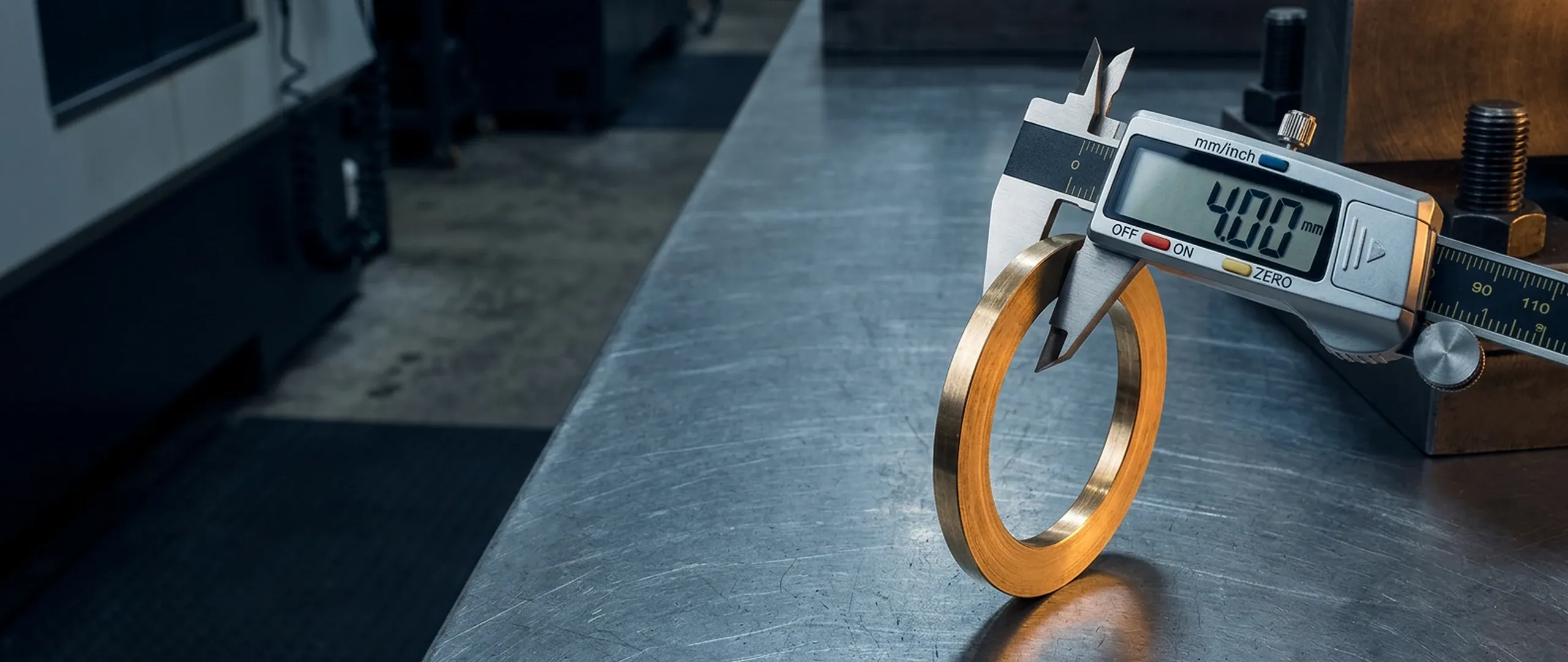
A caliper reads the gasket to its true dimension — but on soft rubber the jaw force compresses the part, which is why ISO 23529 fixes the measuring conditions below.
Measurement Conditions
Measurement conditions affect whether a part reads within tolerance, especially for soft rubber, which responds to temperature and to the cure cycle itself. The following timing and conditioning rules apply when verifying parts against the tolerance classes on this page.
- Wait time after vulcanisation. For solid rubber products, dimensional measurements should not be taken until at least 16 hours after vulcanisation; this is extended to a minimum of 72 hours in cases of dispute, per ISO 23529.
- Inspection window. Measurements should be completed within 3 months of despatch, or before the product is put into use, whichever is shorter. Rubber properties drift on the shelf even before installation.
- Temperature. Condition and measure rubber parts at 23 °C ± 2 °C per ISO 23529. For rigid materials, the standard reference temperature is 20 °C per ISO 2768-1. Allow parts manufactured or stored at significantly different temperatures to equilibrate before inspection.
- Storage and handling. Store and preserve rubber products in accordance with ISO 2230 to keep them within tolerance during the inspection window. Do not distort the part during measurement.
For soft rubber specifically, ISO 23529 also specifies the gauge foot pressure used during measurement (22 kPa ± 5 kPa for hardness ≥35 IRHD, 10 kPa ± 2 kPa below that). If your inspection method differs, results may not match our outgoing QC values.
Worked Example — Environmental Dimensional Changes
Consider a 1000 mm part manufactured in winter at 10 °C and 30% relative humidity (RH), then measured in peak summer at 35 °C and 80% RH. That is a 25 °C temperature swing with a significant increase in humidity.
Values are approximate and vary by grade. Coefficient of thermal expansion (CTE): 316SS ≈ 16 × 10⁻⁶/°C, PTFE ≈ 120 × 10⁻⁶/°C, compressed fibre ≈ 20 × 10⁻⁶/°C, PA6 (Nylon 6) ≈ 80 × 10⁻⁶/°C. Moisture swell is grade-dependent; PA6 is notoriously hygroscopic (up to ~8% water uptake by mass at saturation, which produces a smaller dimensional change than the mass figure — the ≤3% swell noted above is dimensional).
These dimensional changes are a normal property of the material, not a manufacturing defect. We recommend inspecting goods promptly on receipt, while conditions are closest to those at manufacture. If your application involves large parts, tight clearances, or assemblies using dissimilar materials, consider accommodating potential environmental dimensional changes in your design.
Please refer to our Terms & Conditions for inspection and acceptance requirements.
Thickness Tolerances
Thickness tolerance is governed by the sheet manufacturer's standard. It is separate from the cutting tolerance we apply to the part profile.
Soft & Elastic Materials
Sheet thickness is set by the sheet manufacturer, typically to ISO 3302-1 Class ST2 or ST3 (sheet thickness classes, separate from the E and L profile classes). It is independent of the profile tolerance we apply during cutting. For standard stock, we inherit the sheet supplier's thickness tolerance. If your application requires a non-standard or precision thickness, include that requirement in your enquiry — we can source specialist materials.
Rigid & Semi-Rigid Materials
For metal sheet and plate, the relevant supply standard governs thickness tolerances: AS/NZS 1734 (aluminium sheet and strip), ASTM A480/A480M / EN 10029 (stainless steel sheet and plate), ASTM A6/A6M (carbon structural steel). Engineering plastics (PTFE, nylon, acetal) come to us with thickness tolerances set by the grade and supplier. In all cases, the thickness tolerance is independent of the cutting tolerance we apply to the part profile.
Bolt Holes & Hole Position
Bolt holes in a gasket are clearance holes — cut oversize so the gasket drops over the flange studs without binding. Their position is not governed by the gasket's profile tolerance; it follows the mating flange's bolt pattern, which is the datum for the whole joint.
We cut the bolt-hole pattern from the flange drilling standard called out on your drawing — for example ASME B16.5 or AS 2129 — so the holes line up with the studs regardless of the profile tolerance class. If your drawing carries an individual position tolerance on a hole or bolt circle, that callout takes precedence over the general class, exactly as it does for any critical dimension.
Common Tolerance Mistakes
ISO 2768 on Soft Rubber
ISO 2768-1 is written for rigid, machined parts. On compressible rubber its bands are difficult to verify reliably — specify DIN 7715-5 for cut soft parts instead.
A Finer Class Than Needed
Soft gaskets seal by compression, not edge precision. Unless a dimension sits on a critical seal interface, a tighter class adds cost and reject risk without improving the seal — match the class to what the joint actually needs.
Rejecting Before Conditioning
Rubber drifts with temperature and humidity. A part measured out of spec on arrival may simply need conditioning — measure at 23 °C ± 2 °C per ISO 23529 before judging it non-conforming.
Universal Gaskets Policy
Unless your drawing specifies a different tolerance class, these are the defaults we apply to every order. If your application needs tighter control, call it out in your enquiry.
Soft & Elastic
DIN 7715-5 P2 (Medium)
Rubber, cork, foam, compressed fibre, and other compressible sheet materials. P1 (Fine) available on request.
Extruded Rubber
ISO 3302-1 E2 (Medium)
EPDM profiles, silicone strips, and custom extrusions. E1 (Fine) available on request. Cut lengths default to L2.
Rigid & Semi-Rigid
ISO 2768-1 Class m (Medium)
PTFE, metals, engineering plastics, and rigid composites. Fine class available on request.
Specifying Tolerances on Your Drawing
The cleanest way to specify a tolerance class is a single general-tolerance note in the title block. Three worked examples:
GENERAL TOLERANCE: DIN 7715-5 P2 UNLESS OTHERWISE STATED
For cut soft parts — rubber, cork, foam, compressed fibre. Matches our default, so it documents rather than changes what you receive.
GENERAL TOLERANCE: ISO 3302-1 E2 / L2
For extruded profiles — E class governs the cross-section, L class the cut length. Specify both when you dimension both.
GENERAL TOLERANCE: ISO 2768-m
For rigid materials — PTFE, metals, engineering plastics. The standard title-block form on Australian drawings.
As per our Terms & Conditions, these defaults apply unless a different class is specified on the drawing or purchase order.
Where your drawing specifies individual tolerances on critical dimensions (e.g. ∅90 ± 0.05), those tolerances always take precedence over the general class defaults above — both over our defaults and over any title-block note like the examples. If your project requires tighter controls, highlight this in your enquiry.
Explore Further
Unsure Which Tolerance Class to Specify?
Send us your drawing with a quote request and we will quote against the tolerance classes it calls out. No drawing? Tell us the application and we can recommend a workable class.
- DIN 7715-5, ISO 3302-1, and ISO 2768-1
- P2 / E2 / Medium defaults
- Tighter classes on request
Disclaimer
This resource is provided for general engineering reference only and does not constitute professional advice, specification, or guarantee of performance. Actual results depend on specific application conditions. Universal Gaskets Pty Ltd accepts no responsibility or liability for decisions made based on this information. For full terms, see our Terms & Conditions.
Tolerance values are reproduced from DIN 7715-5, ISO 3302-1, and ISO 2768-1 for convenience; always refer to the current published edition of the relevant standard for authoritative data. Actual achievable tolerances depend on material type, hardness, part geometry, and manufacturing method. The material boundaries between standards are approximate, so contact our team for guidance on borderline materials.