
Why Flanges Get Isolated
A flanged joint normally lets electricity pass straight through it. The bolts clamp two conductive flanges together, and current crosses from one pipe to the next without noticing the joint is there. Isolating the joint breaks that path on purpose. We do it for two reasons, and often both at once.
Keep Cathodic Protection Current Where It Belongs
A cathodic protection (CP) system pushes a small protective current onto the pipe you want to keep from corroding. If a flanged joint stays conductive, that current bleeds off into connected steelwork and structures instead of staying on the protected line. An isolating joint pens the current in, so the system protects the section it was sized for.
Stop Galvanic Corrosion at Dissimilar Metals
Where a carbon steel flange bolts to stainless steel or another alloy, the two metals form a galvanic cell and the less noble one corrodes faster. Breaking the electrical path across the joint stops that cell forming, so the dissimilar-metal connection does not eat itself from the flange face outward.
How a Joint Is Isolated
An isolated joint is built from insulating parts, and the two words are worth keeping straight. Insulating is the material property: the sleeves, washers, and gasket will not carry current. Isolated is the result: no metal path runs across the joint. The distinction is real, even though the trade uses insulation kit and isolation kit for the same assembly.
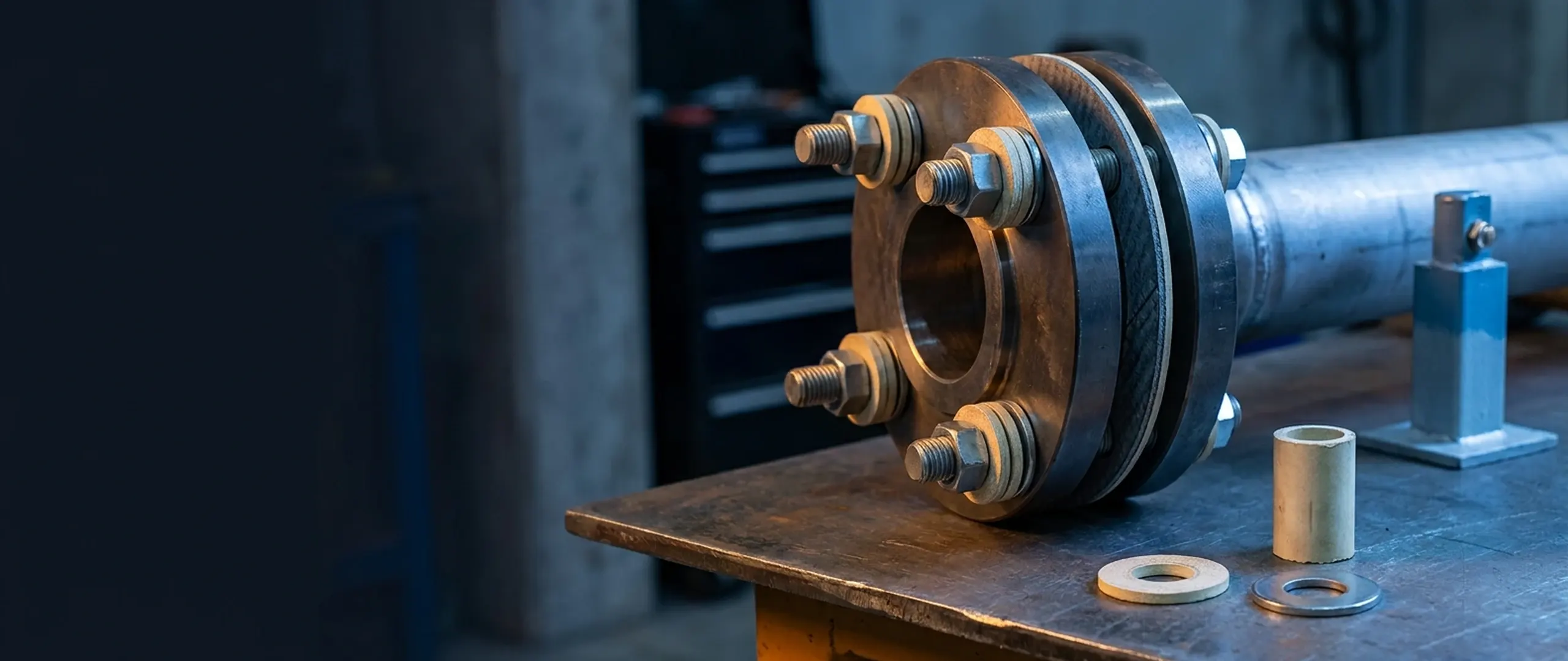
Isolation happens one bolt at a time, backed up by the gasket in the middle. The gasket seals the flange faces and insulates them from each other. Every bolt then gets its own insulating set so no stud can bridge the two flanges. Miss one bolt and the whole joint conducts again, which is why there is no partial version of this.
Amber parts break the circuit.
Select a part to see what it does. Amber parts insulate; grey parts are steel.
The two steel flange rings. Bolt them up bare and the stud touches both bores, shorting the joint. Everything amber in this view is there to stop that.
Sits between the flange faces and blocks the metal-to-metal path across the joint. We supply it as part of a complete kit. See kit types & materials.
The stud carries the clamp load through the joint. It is bare steel, so the sleeve and washers do the isolating around it. Explore Studs, Bolts & Washers.
One bare-steel nut at each end holds the clamp load. They tighten onto the steel backing washers, never straight onto the insulating parts. Explore Studs, Bolts & Washers.
A full-length tube over the stud. It reaches at least halfway into each steel washer, so no bare bolt ever meets a flange bore. More on sleeve length.
One at each end of the stud, inboard of the steel washer, breaking the electrical path under the nut. See sleeve and washer materials.
They spread the nut load across the insulating washer so it does not crush or creep. Always between the insulating washer and the nut. See sleeve and washer materials.
One Per-Bolt Set
Each bolt carries one full-length insulating sleeve over the shank, plus two insulating washers and two steel backing washers, one pair at each end. The sleeve keeps the stud clear of both flange bores. The insulating washer breaks the path under the nut, and the steel washer spreads the clamp load across it.
The Stack, Face Outward
- Flange face
- Insulating washer
- Steel backing washer
- Nut or bolt head
Never Skip the Steel Washer
An insulating washer cannot take nut torque on its own. Without a steel washer to spread the load, it crushes and creeps until steel touches the flange again, and you lose both the seal and the isolation. The steel washer always sits between the insulating washer and the nut, never the other way round.
Those parts come as a single or a double washer set. A double set puts an insulating and a steel washer at each end of the bolt and isolates both flanges, which is the default when you want the joint fully isolated. A single set leaves the insulating washer off one end and bonds the bolt to that flange. You only use it where a drawing calls for one-sided isolation, for example to let cathodic-protection current reach the bolting.
Kits vs Monolithic Isolation Joints
An isolation kit is not the only way to break a joint. The other common option is a monolithic isolation joint, and the two suit very different situations.
Isolation Kit
Field-assembled from separate parts: a gasket, sleeves, and washers you fit on site. It bolts up like any flange and comes apart again, so it suits above-ground joints you can reach, inspect, and re-test. Get the assembly right and it passes the same isolation test as any other joint: the megohmmeter check covered in the testing section.
Monolithic Isolation Joint
A single welded unit with the insulation built into it and sealed at the factory. Nothing is assembled on site and nothing comes apart, which suits buried, permanent, or high-pressure trunk-line joints you cannot risk building in a trench. You trade serviceability for a joint that needs no field assembly.
The short version: above ground and serviceable, reach for a kit; buried and permanent, specify a monolithic joint.
Installing an Isolation Kit
Isolating a joint uses the same bolt-up as any critical flange, with a few extra habits that decide whether the joint reads isolated at the end. Most failed isolation tests trace back to one of these steps, not to the kit. Work through them in order.
- 1
Check bore and bolt-hole alignment first. Pull the flanges up square before fitting anything. A cocked joint drags the sleeve against a bore edge and can shear it as you tighten.
- 2
Fit a full-length sleeve on every bolt. The sleeve runs through both flanges and past the gasket, reaching at least halfway into the steel backing washer at each end, so no bare shank sits inside a flange bore. Every bolt gets one; a single bare bolt shorts the joint.
- 3
Build the washer stack in order at each end: flange face, then the insulating washer, then the steel backing washer, then the nut. The steel washer always sits between the insulating washer and the nut.
- 4
Use matched sleeve and washer sets. Mixing washers from two suppliers is how sleeves get twisted and insulating washers extrude under load. Matched diameters keep both from happening.
- 5
Keep conductive anti-seize off the isolating gap. If a bolt spec calls for anti-seize, keep it on the threads only and away from the sleeve, the washer faces, and the gasket.
- 6
Torque up in a staged star pattern. Isolation does not change the bolt-up itself: tighten in stages, cross-pattern, so the gasket loads evenly. Use the torque figures specified for the kit. Isolating gasket materials often take a lower bolt stress than a bare steel joint. Our Flange & Gasket Installation Guide covers that sequence in full, with an interactive tightening tool.
Workshop Note
Non-conductive is the word that matters with anti-seize on an isolation joint. Copper and nickel pastes conduct, so a smear tracked across the gap or onto a washer face shorts the flange as surely as a missing sleeve. If in doubt, leave the isolating faces clean and dry.
Why Isolation Fails
Isolation is all-or-nothing. One un-sleeved bolt, one crushed washer, or a smear of conductive paste bridging the gap shorts the whole flange, and the joint reads dead no matter how careful you were with the other twenty bolts. The diagram below shows the two ways a single bolt hands the current a path straight across the joint.
The Four Faults That Short a Joint
- A missed or too-short sleeve, so the bare shank touches a flange bore
- A crushed or omitted insulating washer, putting steel back onto the flange face
- Mismatched or extruded washers, twisting the sleeve or squeezing out under load
- Conductive anti-seize, paint, or debris bridging the gasket or the sleeve
Every one of these hands the current a metal-to-metal path. Because any single fault is enough on its own, isolation is checked at the whole-joint level with a test after bolt-up, rather than bolt by bolt.
Testing & Commissioning
Once the joint is bolted up, one measurement tells you whether the isolation took. How you take it depends on where the joint is.
- 1
Test the dry joint with a megohmmeter. Take a reading across the flange with a 500 V megohmmeter. On a dry, above-ground joint, more than 1 MΩ is the commonly accepted pass.
- 2
Test buried or CP-live lines differently. A plain ohmmeter lies across a buried or cathodically protected flange, because the electrolyte around the pipe and the standing DC on the line both corrupt the reading. Use an RF isolation tester, which works around the electrolyte path and does not need the cathodic protection switched off.
- 3
Commission the isolation with the CP system. On a protected line, commission the joint as part of the cathodic protection system under AS 2832.1:2015, so it is verified in the context of the whole line rather than on its own.
These are typical figures and common practice, not a pass certificate for your specific joint. The reading that counts is the one taken on the joint in front of you, under its own service conditions.
Standards for Isolation Work
The standards behind isolation split into two groups. One side governs cathodic protection: why and how a joint is isolated and bonded. The other side fixes the flange dimensions the kit has to fit.
AS 2832.1:2015
Cathodic Protection of Metals
Part 1 covers pipes and cables. It is the Australian anchor for isolation and bonding design, and the standard a protected joint is commissioned under.
NACE/AMPP SP0286-2007
Electrical Isolation of CP Pipelines
Spells out electrical isolation of cathodically protected pipelines, right down to the gaskets, sleeves, and washers that do the isolating.
Which Flange Standard? ASME Is Not the Only One
The gasket and bolting have to match the flange they sit on, and that flange might not be drilled to ASME. ASME B16.5 sets the pipe-flange dimensions most people reach for first. Much Australian pipework, though, is drilled to AS 2129 Table D or Table E, or to AS 4087 for water and wastewater. Those tables dominate utility work, so we supply kits and sleeves to suit the AS drilling as readily as ASME. Tell us the flange standard and we work the bolting back from it.
Related Resources
Isolation touches the gasket, the bolting, and the flange rating all at once. These pages cover the parts and the practice in more depth.
Flange Isolation Kits
Complete Type E, F, and D isolation kits: gasket, sleeves, and washers matched to your flange and pressure class.
Explore Isolation Kits
Bolt Isolation Sleeves & Washers
The per-bolt insulating parts on their own, in Mylar, HDPE, Nomex, PTFE, and G10, for topping up or rebuilding a joint.
Explore Sleeves & Washers
Flange & Gasket Installation Guide
The general bolt-up: star-pattern tightening and staged torque, with an interactive sequence tool. The part isolation shares with every critical flange.
Read the Guide
Specifying an Isolation Kit?
Send us the flange size, pressure class, face type, and service. We'll spec the kit type, gasket material, and bolt hardware, and supply it to suit ASME or AS-table flanges.
Disclaimer
This guide is provided for general engineering reference only and does not constitute professional advice, specification, or guarantee of performance. Actual results depend on specific application conditions. Universal Gaskets Pty Ltd accepts no responsibility or liability for decisions made based on this information. For full terms, see our Terms & Conditions.